



Key Takeaways
- Choose an isolation transformer based on the complete electrical system, not voltage alone.
- Confirm the load’s VA or kVA demand, startup current, and future expansion needs.
- Match primary and secondary voltage, phase, frequency, and connection requirements.
- Understand that isolation can reduce certain ground-loop and interference issues, but does not solve every power-quality problem.
- Proper grounding, bonding, overcurrent protection, and qualified installation remain essential.
- Consider enclosure type, ventilation, ambient temperature, noise, and installation space.
- Check protection coordination, short-circuit requirements, and applicable electrical standards.
- Avoid confusing voltage conversion with galvanic isolation.
- Select a transformer that fits the actual application, safety requirements, and operating environment.
Choosing an Isolation transformer is not simply a matter of matching a voltage rating. The correct unit must fit the load, the electrical system, the installation environment, and the intended safety strategy. A well-planned specification can help protect equipment, reduce certain interference problems, and create a more controlled secondary supply. It is equally important to set realistic expectations. An isolation transformer can provide galvanic separation between source and load, but it does not replace proper grounding, overcurrent protection, lockout procedures, qualified installation, or compliance with applicable electrical rules.
Why Electrical Isolation Matters
Galvanic isolation means there is no direct conductive path from the incoming supply to the output circuit. Instead of sharing a continuous wire connection, the source and load are separated by transformer windings. This can help interrupt some ground-loop paths and limit the transfer of certain common-mode disturbances.
For example, a service bench working on sensitive electronic equipment may benefit from a separate supply that reduces unwanted interactions with the building’s electrical system. However, the secondary circuit can still be hazardous. Touching both secondary conductors or making an incorrect grounding or bonding change can still cause injury or damage to equipment.
How An Isolation Transformer Works
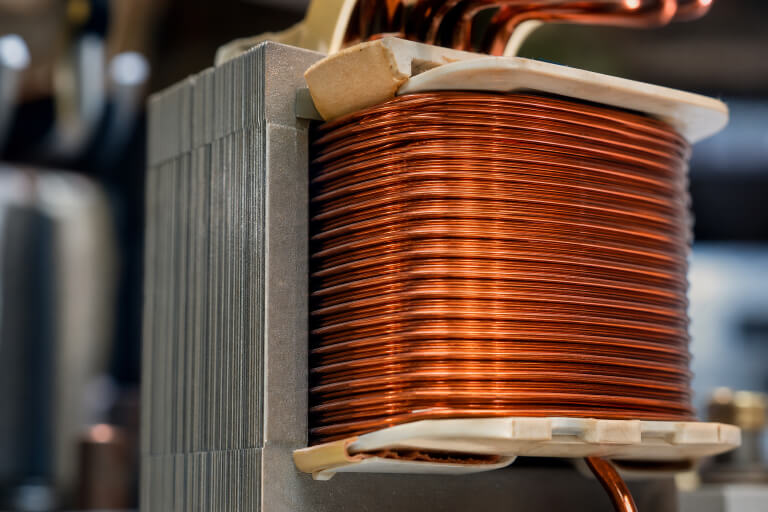
A transformer has a primary winding connected to the supply, a magnetic core, and a secondary winding connected to the load. Alternating current in the primary creates a changing magnetic field in the core. That field induces voltage in the secondary winding, transferring energy without a direct electrical connection between the windings. Voltage conversion and isolation are related but separate functions.
A transformer may step voltage up, step it down, or maintain approximately the same voltage while still providing winding separation. By contrast, an autotransformer uses a shared winding and does not provide the same galvanic separation. That distinction matters when a new grounding reference, reduced loop-current risk, or enhanced separation is part of the design goal.
Where Isolation Transformers Are Used
Applications Defined By Need
Isolation transformers are used wherever the electrical system requires separation, noise management, or a carefully designed output arrangement. Industrial control panels may use them to separate sensitive controls from noisy machine circuits. Data, communications, audio, and measurement systems can use them to address hum, interference, and shared-ground issues.
Laboratory and medical settings may require specially designed power arrangements for sensitive equipment, while maintenance teams may use them to create a more controlled supply for appropriate test work. The application determines the specification. A small transformer for a bench instrument is not automatically suitable for a motor, a compressor, a variable-frequency drive, or a critical continuous process.
Start With The Load
Begin with the equipment that the transformer will actually supply. VA, or volt-amperes, is the basic transformer capacity rating. Larger systems are often expressed in kVA, where one kVA equals 1,000 VA. Collect the steady operating demand, duty cycle, anticipated future loads, and the type of equipment connected.
- Continuous running power and current
- Motor starting current or compressor inrush
- Electronic power supplies, drives, heaters, or nonlinear loads
- Operating hours and peak-demand periods
- Reasonable expansion expected after installation
Do not size solely from normal running current. Motors and some electronic loads can draw a much higher current at startup. Leave a practical design margin, but avoid excessive oversizing, as it can increase costs, occupy more space, and complicate protection coordination.
Match Voltage And Phase Requirements
Confirm both the primary input voltage and the secondary output voltage before selecting a unit. Also, verify whether the system is single-phase or three-phase, its operating frequency, and the required connection arrangement.
For three-phase systems, delta or wye connections, line-to-line voltage, and line-to-neutral voltage can materially affect the design. A nameplate photograph may be useful, but it is not a complete system study. A qualified electrical professional should confirm the supply characteristics, equipment requirements, conductor sizing, protective devices, and installation drawings before ordering equipment.
Power Quality And Electrical Noise
Isolation can help limit some common-mode noise and break circulating ground-loop currents. That can reduce audible hum, communication errors, and measurement instability. It does not automatically solve every power-quality issue. Voltage sags, harmonic distortion, fast transients, poor power factor, and inadequate upstream capacity each have different causes and may require different solutions.
Consider a control system that resets whenever a nearby motor starts. The transformer may help if shared grounding or conducted noise is the issue. If the reset comes from a voltage drop caused by undersized conductors, high starting current, or an overloaded feeder, the solution may instead involve wiring changes, regulation, filtering, surge protection, or load management.
Grounding And Bonding Considerations
The secondary grounding arrangement must be intentionally designed and installed in accordance with the applicable rules. Depending on the system, the transformer may create a separately derived source with specific bonding, grounding-electrode, fault-protection, and maintenance considerations.
Never add or remove a secondary bonding connection as an isolated change. The distinctions among separation, isolation, and shock protection are important because electrical separation and galvanic isolation can serve different safety and functional purposes. The entire installation, not only the transformer nameplate, determines whether the design is appropriate.
Enclosure And Installation Conditions
Location affects transformer life and performance. Identify whether the unit will be indoors or outdoors, exposed to dust, moisture, corrosive agents, vibration, high ambient temperatures, or limited ventilation. The enclosure, mounting method, cable entry, clearance around ventilation openings, and access for inspection all need attention.
Heat is especially important. Restricted airflow or a hot equipment room can raise winding temperature, shorten insulation life, and reduce reliability. Also consider audible sound levels if the transformer will be near occupied workspaces.
Common Specification Mistakes
- Using normal load current while ignoring inrush or startup demand.
- Confusing a voltage-changing transformer with a transformer that provides the required isolation.
- Assuming separation removes every shock hazard.
- Ignoring harmonics and nonlinear load effects.
- Selecting the wrong phase, frequency, or connection arrangement.
- Overlooking ambient temperature, enclosure, and ventilation needs.
- Skipping short-circuit ratings and protection coordination checks.
A Simple Selection Checklist
- Identify the supplied equipment and continuous VA or kVA demand.
- Confirm startup current, inrush, duty cycle, and expansion plans.
- Verify primary voltage, secondary voltage, phase, frequency, and connection type.
- Assess noise, harmonics, ground loops, and other power-quality concerns.
- Define the required grounding and bonding arrangement.
- Review enclosure, cooling, sound, space, and maintenance access.
- Confirm applicable product and installation requirements.
For applications requiring a safety isolating transformer, verify the relevant certification and testing details against the requirements for general applications before finalizing the specification.
Final Takeaway
The best isolation transformer specification starts with the whole electrical system. Load behavior, voltage, phase, grounding, environment, protection, and future growth must all work together. The objective is not the largest transformer or the most complex arrangement. It is a properly sized, properly installed unit that supports the load and the safety plan.
Before installation, review the equipment’s operating and startup demands, confirm the required primary and secondary voltages, and consider whether electrical noise or grounding issues are part of the problem. Installation conditions such as ventilation, temperature, available space, and accessibility should also be evaluated.
Proper protection, grounding, bonding, and compliance with applicable electrical requirements remain essential. By considering these factors together and involving qualified professionals when needed, users can select an isolation transformer that provides reliable performance while supporting the broader safety and operational goals of the electrical system.